Quantcast
Channel: Circuit-Zone.com
Viewing all 149 articles
Browse latest View live

Adjustable Constant Current Load

$
0
0
Adjustable Constant Current Load

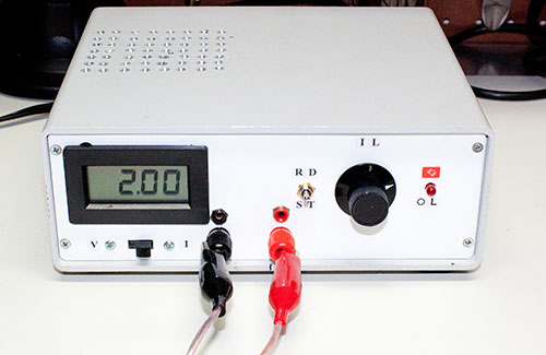
An adjustable power load is a piece of test equipment that often comes handy in the development of a certain electronics projects. For example, when you are building a power supply, it will come a time when you need to "simulate" a load to see how well your design performs as the load varies. Adding power resistors to the output can sometimes do in a pinch, but often you will not have the right resistor value handy with the right power rating for the test. This is where an adjustable electronic load comes handy. In this article, I'll show how you can build one using common components available to the electronics hobbyist.

MAX038 Generator

$
0
0
MAX038 Generator

This is simple MAX038 generator. It produces sine, triangle and square waves from 1Hz up to 22MHz. The Amplitude, offset and duty cycle are adjustable to offer wide range of generated signals. Frequency adjustment is made as a rotary switch S8 with a capacitor bank and variable resistor P7. Amplitude, offset and duty-cycle are performed via variable resistors. Switch S5 selects generated waveform.

Arduino RF link using 433MHz Transmitter / Receiver modules

$
0
0
Arduino RF link using 433MHz Transmitter / Receiver modules

If you are looking into wireless communication between two Arduino modules, this project might be helpful. It uses low costs RF transmitter and receiver from Electronics-DIY.com to establish radio link between two Arduino boards up to 500 ft. Data can be transferred serially at the maximum rate of 2400 bps. The schematic shows how receiver and transmitter is hooked up to two different Arduino boards. When wiring the receiver / transmitter you only need to give them power / ground and then a pin for the TX (serial transmit) or RX (serial receive) pin. I also wired a button to the Arduino doing the transmitting, and used the LED on pin 13 that is built into my Arduino boards on the receiver so I could test this setup. The test app just flashes LED on the receiving board when a button is pressed on the transmitting board.

Adjustable Bench Power Supply

$
0
0
Adjustable Bench Power Supply

If you are starting to learn electronics variable bench power supply is the first thing you should build to power your projects. This simple power supply is built around the LM317/LM338/LM350 linear voltage regulator. The LM317 is one of the most popular voltage regulators on the market, and for good reason. It is very simple to use and requires very few external components. LM317/LM338/LM350 regulators provide a stable and reliable output voltage adjustable between 1.25V and 37V. The short circuit protection is also built right in the voltage regulator.

AM Radio Transmitter Using 555 Chip

$
0
0
AM Radio Transmitter Using 555 Chip

This project shows how to build a simple AM radio transmitter based on 555 timer IC. The circuit parts are: the 555 timer IC, a NPN transistor three caps, three resistors and a potentiometer. The circuit is able to generate an amplitude modulation signal at 600Khz and you are able to receive it using a plain AM receiver. The range is about 30-40 feet.

Simple MOSFET Switch

$
0
0
Simple MOSFET Switch

Constructing a MOSFET switch is one of the basic level electronics projects and could be useful for beginners to get a hang of the various FET transistors. The aim of this project is to make control a heavy duty DC load by constructing a simple switch. MOSFET transistors are capable of handling a large voltage and current. It is because of this feature that it is being much sought after for connecting heavy loads to a circuit or a microcontroller.

1 Watt FM Transmitter Amplifier

$
0
0
1 Watt FM Transmitter Amplifier

This is a 1 Watt FM Transmitter amplifier with a good design that can be used to amplify a RF signal in the 88 – 108 MHz band. It is very sensitive if you use good RF power amplifier transistors, trimmers and coils. It has a power amplification factor of 9 to 12 dB (9 to 15 times). At an input power of 0.1W the output will be 1W. You must choose T1 transistor depending on applied voltage. If you have a 12V power supply then use transistors like: 2N4427, KT920A, KT934A, KT904, BLX65, 2SC1970, BLY87. At 18 to 24V power supply you must use transistors like: 2N3866, 2N3553, KT922A, BLY91, BLX92A. You may use 2N2219 at 12V but you will get an output power of 0.4W maximum.

4km FM Transmitter

$
0
0
4km FM Transmitter

This is a VCO FM Transmitter. With good antenna (dipole placed outdoor and high) the transmitter has very good coverage range about 500 meters, the maximal coverage range is up to 4 km. To calibrate for maximum power connect 6 V / 0,1 light bulb to the output and use R1 to tune the right frequency, adjust L1 coil if necesary. Then use C14 and C15 to adjust the highest power (the highest light of the bulb). Then you can connect antenna and audio signal. Adjust R2 until the audio sounds as loud as the other stations.

Plant Water Alarm

$
0
0
Plant Water Alarm

This simple plant water alarm circuit indicates when the soil is dry and the plant needs watering. The circuit does not have a current-limiting resistor because the base resistor is very high and the current through the transistor is only 2mA. Replacing 220K resistor with 1M potentiometer will provide adjustment when the alarm should be triggered depending on the moisture left in the soil.

27MHz Walkie Talkie

$
0
0
27MHz Walkie Talkie

This classic walkie talkie consists of both 27MHz transmitter and receiver all in one circuit. Nearly all the components in the 4-transistor circuit are used for both transmitting and receiving making it simple to build and economical at the same time. The frequency-generating stage only needs 27MHz crystal to be removed and it becomes a receiver. Next is a three transistor audio amplifier with very high gain. The first transistor is a pre-amplifier and the next two are wired as a super-alpha pair, commonly called a Darlington pair to drive the speaker that is also used as a microphone. The use of telescopic antenna will provide better reception and transmitting range. Use two identical walkie talkie circuits for two way communication.

Phone Transmitter

$
0
0
Phone Transmitter

This small phone transmitter will transmit a phone conversation to an FM radio on the 88-108MHz band. It uses energy from the phone line to transmit the signal about 100 meters away. It uses the phone wire as the antenna and is activated when the phone is picked up. Transmitter components are mounted on a small PC board. PC layout is included.

USB Battery Pack

$
0
0
USB Battery Pack

This project is able to power a USB device using two standard AA batteries and an electronics circuit. The circuit is based on LT1073 DC/DC converter to convert the 3V to 5V needed by USB. In that way it can power the USB device on the go.

Automatic Garden Light

$
0
0
Automatic Garden Light

This circuit automatically turns on and illuminates the LEDs when the solar panel does not detect any light. It switches off when the solar panel produces more than 1v and charges the battery when the panel produces more than 1.5v + 0.6v = 2.1v.

Mini FM Transmitter

$
0
0
Mini FM Transmitter

Here's how to build your own mini FM transmitter. It transmits FM waves so you could easily receive the signals on your mobile phone, radios, etc. As the name and the picture indicates it is very small and is approximately the size of a 9v battery clip. With this FM transmitter you could start your own mini FM station. The circuit uses BC547 transistor to amplify the signal and then frequency modulate it. It uses "frequency modulation" most commonly known as FM, the same principal to transmit audio signals captured by the microphone.

LM386 Utility Amplifier

$
0
0
LM386 Utility Amplifier

It's always handy to have a little amp kicking around to trace audio signals, test mics, CD tape and TV audio outputs. You know, something that doesn't weigh a lot and isn't clumsy. There are tons of uses for this little circuit. There are a couple of versions of this amplifier chip. Both are 8 pin DIP packages and the difference between the two are apparent by their part numbers. Either are suited for this circuit provided the supply voltage does not exceed the recommended 5 to 12 volt DC range. Power output can range from about 325 mW to about 750 mW within this supply range when using an 8 ohm speaker. Power it with batteries or a small DC supply...why not solar cells or a little windmill generator?

Automatic Night Light

$
0
0
Automatic Night Light

This circuit automatically turns on the light through a relay when daylight intensity falls below a preset level on the Light Dependent Resistor (LDR).

Curious C-Beeper

$
0
0
Curious C-Beeper

Curious C-Beeper is a fun to build little probe that can be used to quickly detect the capacity of capacitors in pF nF range, test their stability with temperature changes, find broken wires, locate wires, trace wires on PCBs, and to locate live wires behind the walls without touching them. The circuit uses three transistors to make a most unusual capacitance beeper probe. When a capacitor is touched to the probe, the probe beeps at a frequency that varies with capacitance. The frequency change is so steep with capacitance that tiny capacitors may be precisely matched or an exact fixed value may be selected to replace a trimmer in a prototype. If the user has reasonably moist skin, simply holding one lead of the capacitor to be tested while touching the other lead to the probe is all that is necessary. The user's body forms the other connection through the beeper's metal case. When the beeper is properly adjusted it draws only 10 uA with nothing touching the probe - no power switch is required. This design is optimized for capacitors less than about 0.1 uF (100 nF). Large capacitors give a low frequency "clicking" sound and small capacitors sound a tone that increases as the capacitance decreases. Many decades of frequency change occur over the beeper's range giving even the more tone-deaf among us sufficient change to discern slight differences in capacitance. The entire device is powered by two CR2032 lithium cells that fit into TicTac box. The use of power switch is unnecessary since the circuit consumes almost no power when not being used.

Easy FM Transmitter

$
0
0
Easy FM Transmitter

The figure shows a schematic of an easy to build FM transmitter circuit. Mostly all FM transmitter circuits you will find online or in books require some kind of hand build inductor/coil and after building the transmitter you have to adjust that coil and trimmer capacitor a little to adjust the transmitter to transmit on your desired frequency. If you are looking for an easy or simple FM transmitter circuit in which you don't have to make a coil with your hand then the circuit given here is ideal for you. The circuit is using a ready made 1uH inductor which can be purchased from an electronic components store. These inductors are mostly look like resistors. The circuit also does not require a trimmer capacitor, because we have used a fixed value of 39pF capacitor in the place of trimmer capacitor. We have already calculated and used the values of coil and capacitors of oscillator to broadcast on FM band, so you don't have to do any further adjustments and tuning after building the circuit. The circuit can be operated with 9 to 12 volt DC. For antenna use a 12 inch wire or for maximum range use a 30 inch wire and make it vertical.

12V Fluorescent Light Inverter

$
0
0
12V Fluorescent Light Inverter

This is a low voltage 12V fluorescent inverter for powering two 20W or single 40W fluorescent tube. It's a circuit you can put together from junk box components and is a very simple to build. The transformer is hand-wound on a ferrite rod from an old transistor radio and the winding wire can be salvaged from an old transformer. The cost of powering the circuit is about 22 watts and this will produce the same light output as 60 watt incandescent light bulb.

Battery Powered Amplifier

$
0
0
Battery Powered Amplifier

This is battery powered amplifier based on LM386 chip and has an input buffer that is feeding the inverting input. The input buffer helps to retain treble details going into the LM386 chip. It is powered from a single 9V battery.
Viewing all 149 articles
Browse latest View live