September 20, 2013, 7:26 pm
This circuit provides an FM modulated signal with an output power of around 500mW. The input microphone pre-amp is built around a couple of 2N3904 transistors (Q1/Q2), and audio gain is limited by the 5k preset trim potentiometer. The oscillator is a colpitt stage, frequency of oscillation governed by the tank circuit made from two 5pF ceramic capacitors and the L2 inductor. The output stage operates as a 'Class D' amplifier, no direct bias is applied but the RF signal developed across the 3.9uH inductor is sufficient to drive this stage. The emitter resistor and 1k base resistor prevent instability and thermal runaway in this stage.
↧
September 20, 2013, 7:26 pm
![Portable FM Transmitter]()
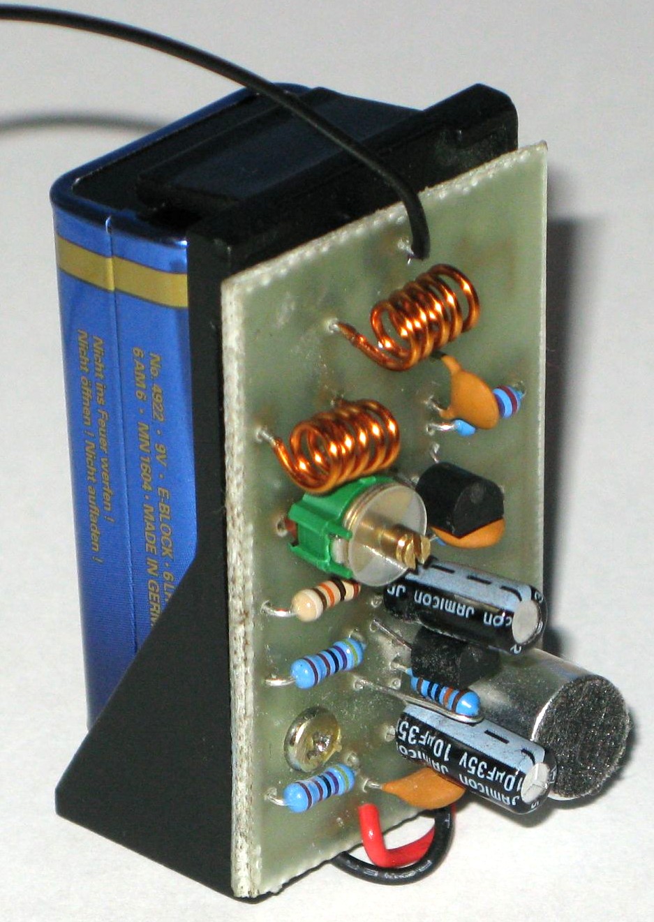
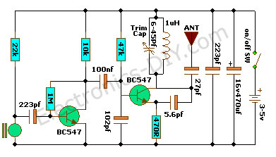
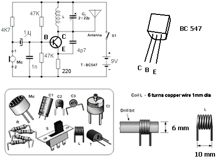
This portable FM Transmitter is easy to build. I have used a pair of BC548 transistors in this circuit. Although not strictly RF transistors, they still give good range. Transmitter is powered by 9V battery. The coil L1 consists of 7 turns on a quarter inch plastic former with a tuning slug. The tuning slug is adjusted to tune the transmitter. Actual range on my prototype tuned from 70MHz to around 120MHz. The aerial is a few inches of wire. Lengths of antenna wire should be 1 - 2 feet. The circuit is basically a radio frequency (RF) oscillator that operates around 70-120 MHz. Audio from audio jack is fed into the audio amplifier stage built around the first transistor. Output from the collector is fed into the base of the second transistor where it modulates the resonant frequency of the tank circuit by varying the junction capacitance of the transistor. Junction capacitance is a function of the potential difference applied to the base of the transistor. The tank circuit is connected in a Colpitts oscillator circuit.
↧
↧
September 20, 2013, 7:26 pm
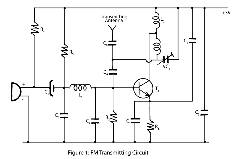
This FM transmitter is about the simplest and most basic FM transmitter it is possible to build and have a useful
transmitting range. It is surprisingly powerful despite its small component count and 3V operating voltage. It will
easily penetrate over three floors of an apartment building and go over 300 meters in the open air. The circuit
we use is based on a proven Australian design. It may be tuned anywhere in the FM band. Or it may be tuned
outside the commercial M band for greater privacy. (Of course this means you must modify your FM radio to
be able to receive the transmission or have a broad-band FM receiver.) The output power of this FM Tx is below
the legal limits of many countries (eg, USA and Australia). However, some countries may ban ALL wireless transmissions without a license. It is the responsibility of the builder to check the legal requirements for the operation of this circuit and to obey them.
↧
September 20, 2013, 7:26 pm
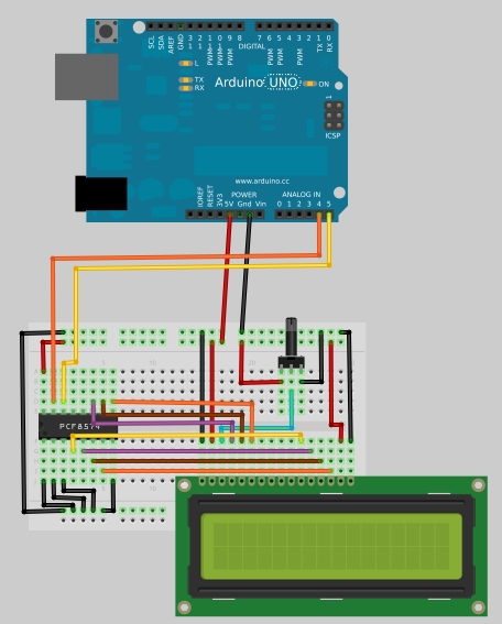
In this tutorial you will learn how to build a simple serial 16x2 LCD display that is controlled via Arduino board by only two wires. The magic behind is done by the PCF8574 chip, an I/O expander that communicates with the micro-controller by using I2C protocol. The PCF8574 is a quick and easy solution to extending and adding output/input ports to Arduino. The chip connects to a standard I2C bus and adds an additional 8 output ports. A total of 8 LCD displays can be connected to the same two wire I2C bus with each board having a different address.
↧
November 17, 2013, 11:28 pm
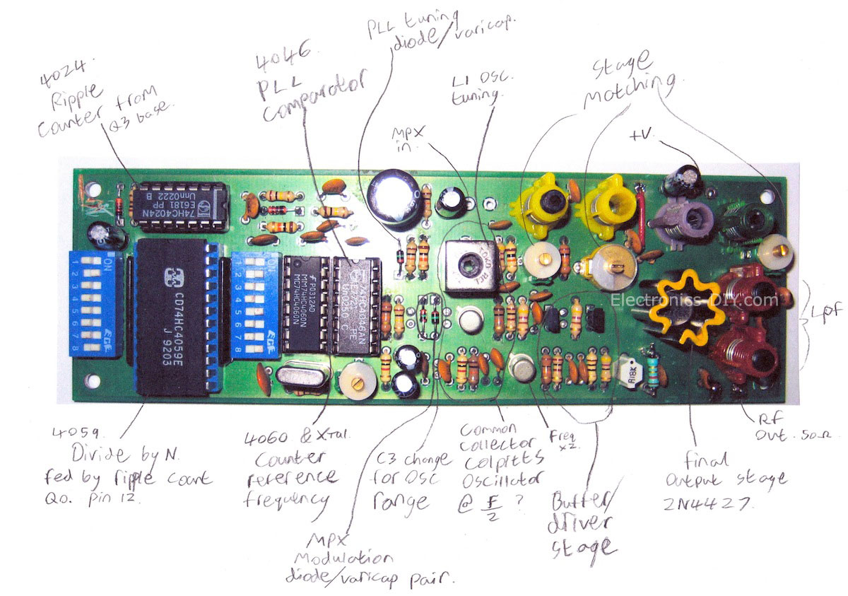
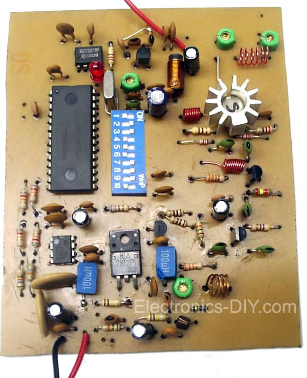
This is a 1 Watt PLL FM broadcast transmitter. The RF output varies from 500mW to about 1.2W depending on the frequency selected and RF output transistor used. Motorola 2N4427 always seems to work well. Transmitter uses CMOS PLL VCO that prevents the frequency drifts. The frequency is selected via DIP switches. The transmitter is supplied by 12V DC and can also be powered from the battery.
↧
↧
November 17, 2013, 11:28 pm
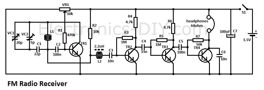
This FM radio receiver circuit is very simple to build and is powered by just a single 1.5V battery cell. Receiver consists of a regenerative rf stage, TR1, followed by a two of three-stage audio amplifier, TR2 to TR4. In some areas 3 stages of audio amplification may not be necessary, in which case TR3 and its associated components can be omitted and the free end of capacitor C5 connected to the collector of TR2.
The critical part of the fm radio receiver is the first stage, TR1/VC1, where the wirings must be kept as short as possible. Coil L1 is formed by winding 8 turns of 1mm (20 swg) enamelled copper wire on a 6 mm diameter former, which is then removed. After that L1 should be stretched carefully and evenly to a length of about 13mm.
↧
November 17, 2013, 11:28 pm
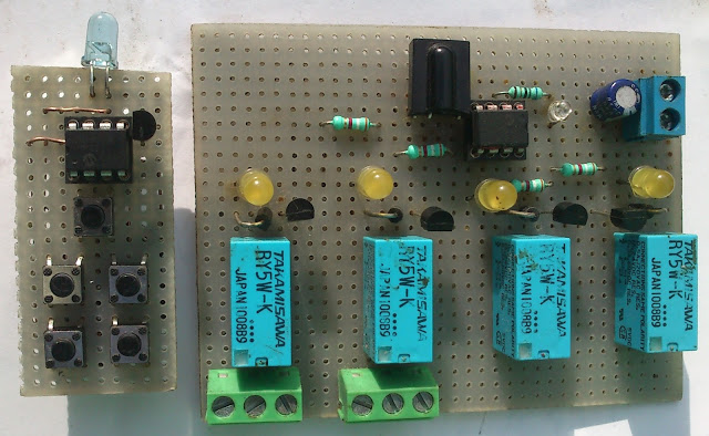
This little project will demonstrate how you can use NEC IR protocol based TV, DVD or VCR remote control to control you home appliances like fan bulb or virtually anything. There are lots of projects out there to accomplish this task but i have to write my own code because of too many requests on IR infrared Remote Control Relay Board with PIC12F675 Microcontroller. There are a number of consumer Infrared protocols out there and they have been used for every single purpose possible, like PDA laptops and other consumer appliances. RC-5 & RC-6 by Phillips, RCA are few examples of consumer IR protocols.
↧
November 17, 2013, 11:28 pm
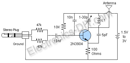
A simple MP3 FM transmitter circuit shown here can be built easily in few minutes if all parts are available to you. All the components used in this transmitter circuit are general purpose and low cost. The circuit will work as a best FM transmitter for simply broadcasting your music around your house and yard, and can be used to broadcast the output of any equipment like mp3 player, ipod, satellite, etc.
↧
November 21, 2013, 8:51 pm
This is simple FM transmitter for FM broadcast band in 88-108 MHz. BC 549 is small signal transistor for wide applications, but usually for AF. You can build simple FM transmitter with one BC549 transistor and several other component parts. Simple FM transmitter with only one transistor is often called “bug”. This project is suitable for beginners in radio amateur, education, or hobbies. As an antenna you can connect 150cm of copper wire.
↧
↧
December 10, 2013, 10:49 am
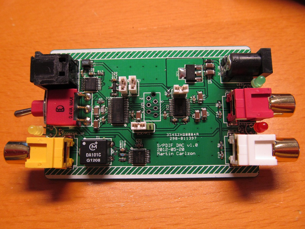
This DAC is based on DIR9001 and the new 384K/32bit PCM5102 DAC from Texas Instruments. PCM5102 DAC features COAXIAL S/PDIF and optical inputs connected to DIR9001 low jitter digital receiver. PCM5102 uses a next generation architecture based on the PCM1792 (TI's flagship 132dB DAC). It is a 112dB Stereo DAC, with an integrated negative rail charge pump and line driver, so you don't need any opamps at the end, just a simple RC Low pass filter is all that is needed. In addition, there's a fancy PLL involved that will autodetect your I2S rate, configure the device, and generate it's own internal master clock so no need for external clock. All DAC chips are powered by onboard 3.3V 1117-33 regulator. DAC should be powered by 5-15V DC voltage.
↧
December 12, 2013, 8:08 pm
Here is a very interesting and simple FM transmitter used to transmit audio in the wide range up to 100M using only one transistor. The entire circuit of FM transmitter is divided into three major stages oscillator, modulator and amplifier. The transmitting frequency of 88-108 MHz is generated by adjusting VC1. The input audio generated by microphone is changed into electric signal and is given to base of transistor T1. Transistor T1 is used as oscillator which oscillates the frequency of 88-108 MHz. The oscillated frequency depends upon the value R2, C2, L2 and L3. Transmitted audio from FM transmitter circuit can be received by standard FM receiver.
↧
December 15, 2013, 9:52 am
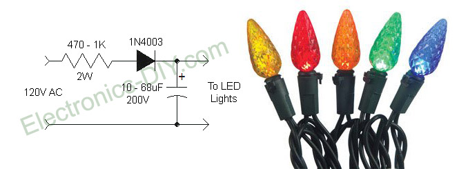
I like the idea of using LED Christmas lights because they look cool and consume very small amount of electricity, but the flicker drives me crazy! That's because they are powered directly from 110V AC voltage instead DC voltage which makes them flicker 60 times per second. Here is a simple circuit that will completely eliminate LED Christmas lights flicker. The solution is to convert AC to DC voltage with resistor, rectifier diode and capacitor. Using 470 ohm - 1K resistor is very essential because it limits the current to 20mA and minimizes the voltage to about 80 volts. If we didn't use the resistor LEDs would be powered by over 50mA of current which is much more than what they need and that would definitely shorten their life. Note that lowering voltage does not reduce the brightness of the LEDs because when powered by DC voltage they are always on.
↧
December 23, 2013, 4:10 am
Following 1W PLL transmitter exciter provides stable, low noise operation. Transmitter uses a PLL frequency synthesizer built with MC145152 which covers the FM band in 100kHz steps. The VCO uses MV2109 varicap diode to automatically tune to selected frequency via SW1 dip switch. output stage uses 2N4417 RF power transistor and provides 1W of RF power. With good antenna expected transmission range is 2km. Transmitter may be built on a double sided PCB, with top side copper left mostly undisturbed as a ground plane. The copper is removed only around non-grounded pins. The ground connections can be soldered on the top side, so it’s not necessary to have plated-through holes.
↧
↧
January 4, 2014, 12:31 am
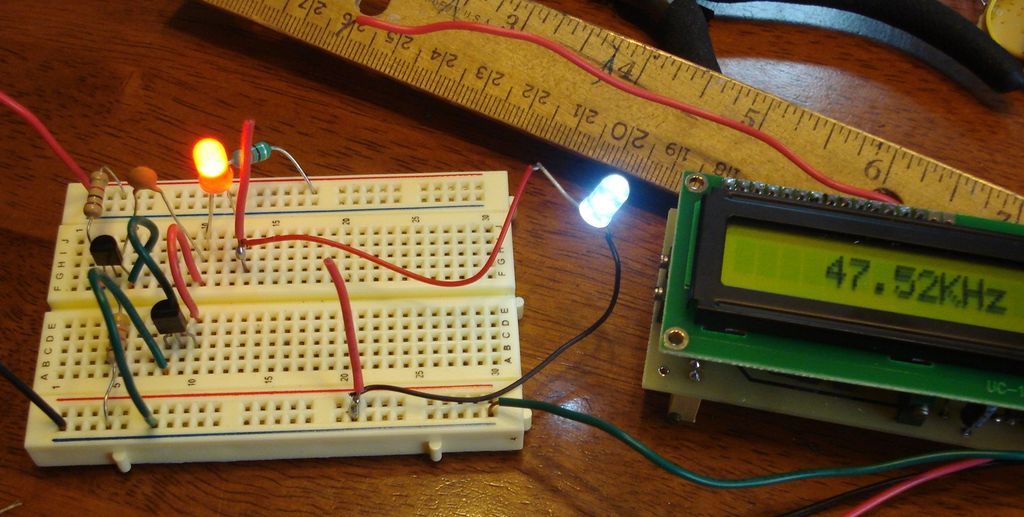
The "Joule Thief" circuit that does not use a transformer to power LED from a single 1.5V battery cell. The circuit consists of two bipolar transistors, coil, two resistors and capacitor to generate higher voltage through 50KHz frequency to power an ordinary LED. Entire circuit draws only about 15 milliamps.
↧
January 4, 2014, 12:31 am
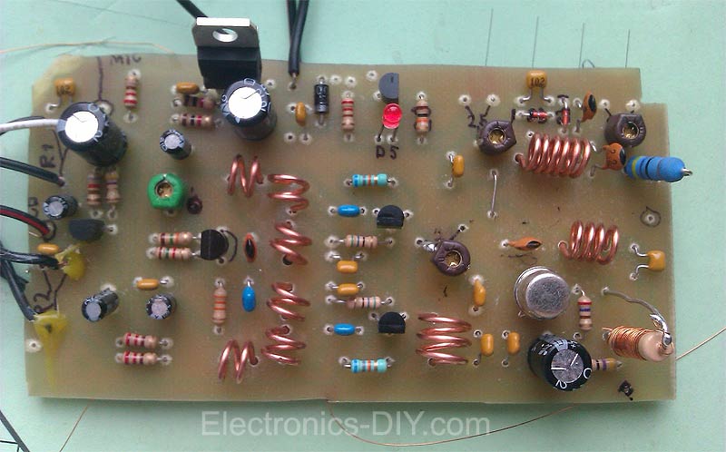
Veronica 1W FM transmitter is an easy to build transmitter. Veronica is also known for frequency stability, clean FM signal and uses no integrated circuit. The Veronica oscillator is actually formed from 2 oscillators which operates somewhere around 50 MHz in anti phase and the 2 signals are combined to form 100MHz FM radio signal. This kind of circuit design is stable and is amplified up to 1W by 2n4427 transistor. Veronica transmitter is equipped with a mini-mixer and so you may forget an external mixer. This consist from T1 transistor which amplifies the microphone signal before it is combined with cd-player audio or PC signal. R1 and R2 are potentiometers (variable resistors) used to adjust the audio level. The component between R8 and C21 represents the oscillator wich generates radio signal. D1 is a varicap diode (like a variable capacitor or trimmer) controlled by audio signal. C12, C13 and L1 determines the frequency.
↧
February 6, 2014, 3:54 pm
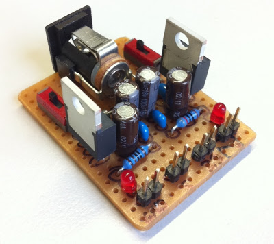
I normally use a USB port as power supply for my projects but some ICs need 3.3V instead of 5V. Therefore I decided to build this small dual power supply. Power supply uses two low dropout voltage regulators that provide up to 800mA of output current and come in TO-220 package. LD1117V33 is used for 3.3V and LD1117V50 for 5V. Input voltage is 6V-15V and both regulators can be switched on/off individually.
↧
February 6, 2014, 3:54 pm
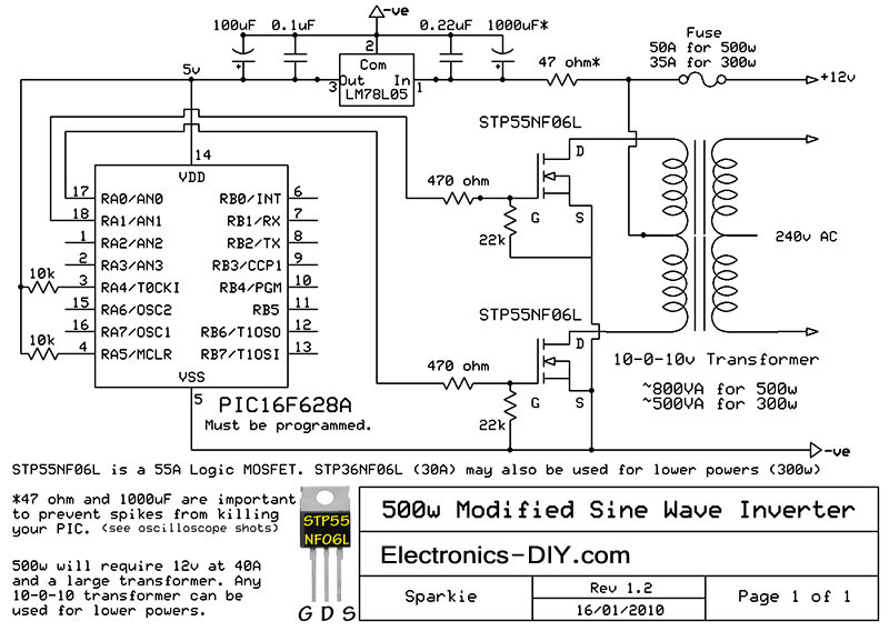
Here is a simple but powerful, stable and efficient schematic diagram for a 500W modified sine wave inverter circuit. Originally I used a 555 timer and a CD4017 decade counter to produce the modified sine wave, but then I thought a simple PIC micro controller with its internal clock would produce a stable 50Hz/60Hz frequency without the need for two ICs. As you can see its a very simple circuit. 220V transformer should be used for 220V voltage output. For 110V voltage output use transformer with 110V rating.
↧
↧
February 22, 2014, 7:58 am
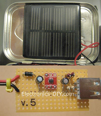
As the world around us becomes more and more environmentally conscious, alternative energies such as solar power are becoming more and more popular. The following solar charger is very simple and inexpensive to build and could be used to charge cellphones, tablets and other USB devices. 6V solar panel could be easily salvaged from outdoor garden lights. Solar charger uses REG113-5 efficient low dropout regulator that only loses 250mv of forward voltage. Linear style regulators such as a LM7805 or LM317 type voltage regulators lose as much as 2-3V and can not be used in this application. Optionally you may also add four-resistor voltage divider to charge an iPhone or iPad.
↧
February 22, 2014, 7:58 am
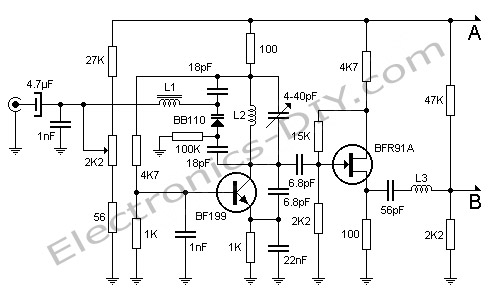
Here's FM transmitter for commercial FM band that provides 18 watts of power. Since the electronic diagram is too large we decided to divide it into two parts. The first part is the actual FM transmitter while the second part is 18W RF amplifier. The circuit should be built on an epoxy printed circuit board with the upper face components reserved for interconnecting tracks and the bottom solder to the ground plane. If powered by 14V and 2.5A transmitter outputs 15W of power, whereas 18V and 3.5A will provide 18W. BB110 variable capacitor connected to the collector of transistor BF199 adjusts the transmission frequency of the circuit. 2K2 potentiometer serves as fine tuning. Once the output frequency is adjusted amplifier variable capacitors must be adjusted for maximum output power one stage at a time. All adjustments must be made with 50 Ohm dummy load connected to the output of transmitter.
↧
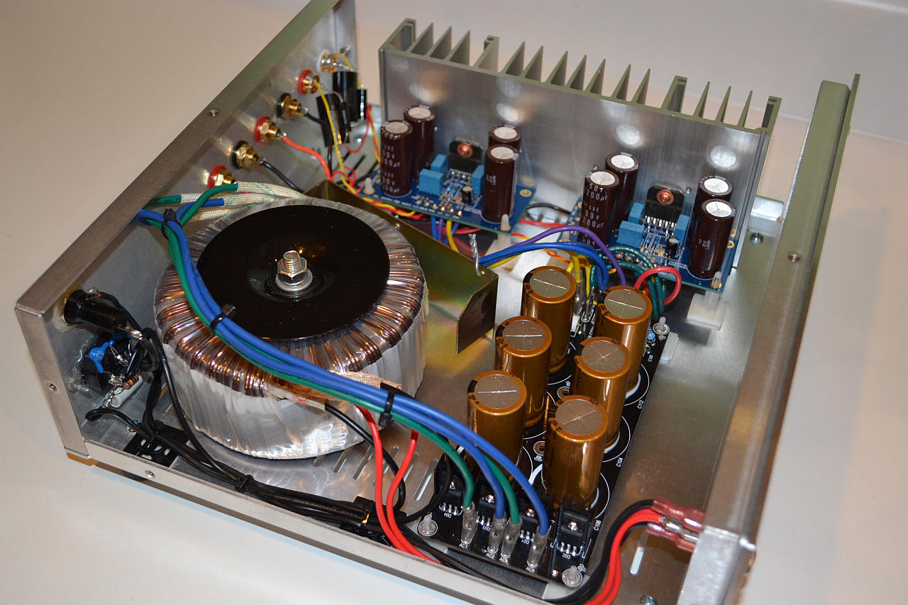
LM3886 is a high-fidelity audio power amplifier IC capable of delivering 68W of continuous power using 4 Ohm speakers. LM3886 provides excellent S/N ratio of 92dB and above as well as extremely low total harmonic distortion over the audio spectrum.
LM3886 comes equipped with Self Peak Instantaneous Temperature Protection Circuitry (SPiKE) that makes it a class above other discrete and hybrid amplifiers. SPiKe Protection makes LM3886 amplifier safe against problems like over voltage, under voltage, overloads, shorts to the supplies, thermal runaway, and temperature peaks.
↧